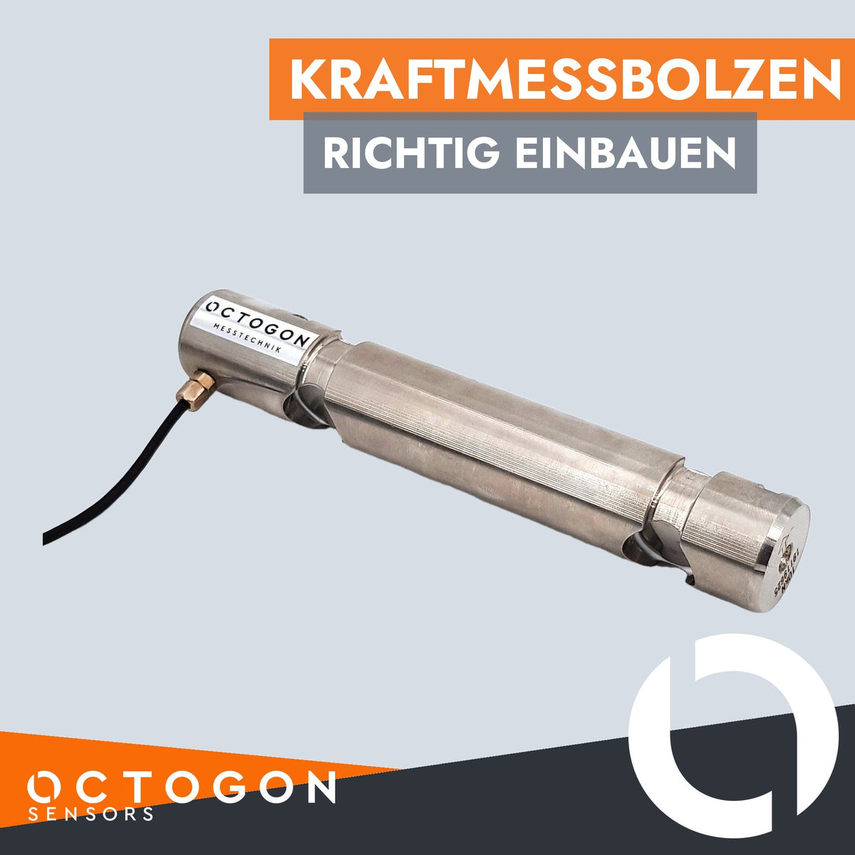
A load pin is a measuring instrument that is installed like a machine element. That is its advantage, and it is also the most common source of error: the pin only measures correctly when it sits and is loaded the way it was designed and calibrated. This article sums up what matters during installation – from the measuring direction and anti-rotation locking to the zero point in the controller.
The measuring direction is fixed
The strain gauges sit in the machined deformation zones and measure shear deformation in one particular direction. That measuring direction is fixed by the design and shown on the installation drawing. If the pin is installed rotated, it only sees the share of the force that falls into its measuring direction. The reading drops with the cosine of the angle:
| Angular error | Reading too low by |
|---|---|
| 2° | 0.06 % |
| 5° | 0.38 % |
| 10° | 1.5 % |
| 15° | 3.4 % |
| 30° | 13.4 % |
Small angles are harmless, large ones are not. Worse than a fixed angular error is a pin that slowly rotates during operation: the error then wanders and the measurement is no longer reproducible. Where the direction of force itself changes, for example at rope pulleys with a varying wrap angle, careful installation does not help – that calls for a biaxial load pin that measures in two directions.
Anti-rotation and axial locking
To keep the pin in its measuring direction it needs a positive anti-rotation lock. Proven solutions are a milled retaining plate that engages a groove or flat on the pin head, or a flat that sits in a matching seat. The retaining plate usually also provides axial locking. A friction connection alone, such as a clamping screw, is not enough: under alternating load and vibration the pin will rotate sooner or later.
When you replace an existing pin, we carry the existing locking over into the design so nothing on the machine has to change. If no anti-rotation lock is provided so far, talk to us before production starts.
Supports, gap and load introduction
A load pin measures the shear force between the outer supports and the load-bearing centre section. The deformation zones must therefore sit exactly in the gaps between link plate and clevis. If the centre section shifts axially because spacers are missing or play is too large, the load acts at a different point and the characteristic value no longer matches the calibration. For the same reason we calibrate load pins in a replica of the installation with your support widths and gaps.
- Double shear is the normal case: the pin sits in a clevis with two supports and the load acts in the middle. The force is split over two shear planes.
- Single shear means the pin is supported on one side only and the load acts overhung next to it. An additional bending moment acts here and must be part of the design. We make single-shear pins on request; we need to know the installation exactly.
- Fits apply as given on the drawing. Too much play shifts the load introduction and encourages impact loading; too tight a fit creates forces during installation that show up as a zero offset.
- Only the measured force should pass through the pin. Otherwise forces from preloaded structures, thermal expansion or misaligned link plates end up in the reading as well.

During installation
- Do not drive the pin in with a hammer. Blows create peak forces far above the rated load and can permanently deform the measuring zones. If it sticks, the cause is fit, alignment or dirt, not too little force.
- Align the bores before inserting the pin, and do not use the pin to align the link plates.
- Never pull or turn the pin by its cable or connector.
- If the pin has lubrication bores, grease the bearing points through the grease nipple as usual.
- Check the measuring direction against the drawing once more before tightening the lock.
Routing the cable
Mechanically, the cable is the most sensitive part. Lead it away from the pin with strain relief, respect the permitted bending radius and protect it at edges and chafing points. If the pin moves, for example on a jib, it needs a drag-chain cable. Do not run signal cables parallel to motor or welding cables. For pins that are exchanged, a connector such as M12 is more practical than a fixed cable.
Zero point and sign
After installation, the zero point is set in the installed, unloaded state. This tares the weight of pulley, hook or lifting accessory and compensates small installation forces. Note this zero value: later it is the simplest check of whether anything has changed on the pin.
Which load direction produces a positive signal depends on the wiring. With a passive mV/V output, the sign can be reversed at the measuring amplifier. With integrated electronics providing 4–20 mA or 0–10 V, the assignment is fixed at the factory. So state in your enquiry in which direction the load acts and which direction should be positive.
In short
- Install in the measuring direction shown on the drawing; small angles cost little, a rotating pin costs a lot.
- Provide positive anti-rotation and axial locking.
- Keep support widths and gaps as used for calibration.
- Do not hammer it in, do not pull on the cable.
- Route the cable with strain relief and away from power cables.
- Set the zero point in the installed state and note it.
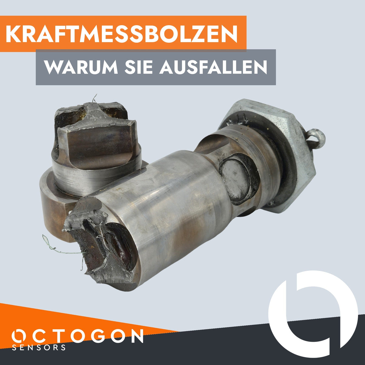
More on designs, signals and safety levels is on the page load pins and measuring axles. What can damage a pin in operation is described in Why load pins fail. Send us your installation drawing at office@octogon.org, call +43 676 3628453 or use our contact form. We look at the installation before anything is made.