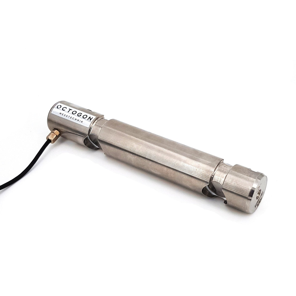
A correctly designed and installed load pin has no wearing parts and works for many years without maintenance. When one fails, the cause is almost always outside the pin: a load nobody expected, welding on the machine, water in the connection or a damaged cable. Here are the most common causes and how to avoid them at the design stage.
Overload and impacts
A standard pin withstands up to the limit load of 150 % of rated load without permanent change; the breaking load is 300 %. Anything beyond that deforms the measuring zones plastically. The catch: the static load of a system is usually well known, impacts are not. A load dropping into the rope, a drive starting with a jerk or a hard stop at the end position can briefly create a multiple of the static load.
- Choose the rated load so that peaks in operation also stay below the limit load.
- For applications with impacts, choose increased limit and breaking loads, for example 300 % and 500 %.
- Do not use a hammer during installation, see Installing load pins correctly.
Overload damage usually shows as a permanent zero offset: in the unloaded state the pin no longer shows the value it had after installation.
Welding on the machine
Welding near an installed pin is a common and easily avoidable cause. Two things do damage: the welding current, if it finds its way through the pin, and the heat, if welding happens close to the pin. The current can break down the insulation between measuring bridge and housing; the heat can damage the adhesive under the strain gauges.
- Remove the pin before welding whenever possible.
- Otherwise attach the earth clamp right next to the weld so no current flows through the pin, and disconnect the signal cable from the electronics.
- Keep heat input near the pin as low as possible.
Temperature
The full bridge compensates temperature effects in the range of -40 to +80 °C. Outside this range the pin measures less accurately, and permanently excessive temperature ages adhesive and cable. For steelworks, foundries and furnace technology there are versions for high temperatures up to 250 °C. Also consider heat that does not come from the surroundings: radiation from a furnace or a warm bearing point.
Moisture and condensation
Water is the enemy of every measuring bridge. It rarely enters as a jet but usually quietly: through an open connector, a damaged cable gland or as condensate when a pin draws in humid air after rapid temperature changes. Moisture in the bridge shows as a slowly drifting zero.
- Choose the right protection class: IP65 or IP67 for most industrial applications, IP69K for high-pressure or steam cleaning.
- Provide hermetically welded housings for underwater use and high-pressure cleaning.
- Always close unplugged connectors with a protective cap.
- Route cables so that water does not run along the cable to the pin.

Corrosion and chemicals
As standard, we make load pins from high-strength stainless steel, usually 17-4PH. That covers harsh industrial environments. Aggressive cleaning agents, salt water or process chemicals, however, also attack stainless steel, seals and cable sheaths. Tell us in your enquiry which media the pin comes into contact with, and we choose material, seal and cable accordingly.
Cable damage
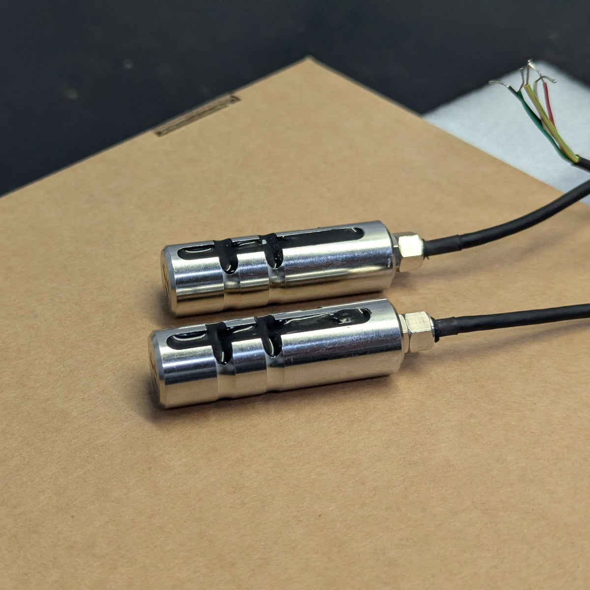
Mechanically, the cable is the most sensitive part of a measuring chain. Crushed, chafed or torn cables are a common cause of signal failures that at first look like sensor damage. Strain relief, edge protection and an adequate bending radius prevent most of it; moving applications need a drag-chain cable. Where pins are exchanged often, a connector such as M12 is better than a fixed cable.
When the pin no longer measures correctly
Before removing a pin, a few simple checks are worth it:
- Compare the zero in the unloaded state with the value after installation. A fixed offset points to overload, a drifting one to moisture.
- Current loop below 4 mA: this is not a reading of zero but a fault, usually a broken line or missing supply.
- Jumping values point to cable, connector or coupled interference rather than to the pin itself.
- Plausibility: check with a known load if the system allows it.
Send us these observations and we will tell you whether a check or recalibration in our calibration laboratory is worthwhile. Where a failure must not happen, for example in hoists, a redundant pin with two independent measuring bridges is the better choice: the two channels monitor each other, see functional safety SIL / PL.
Think of the causes in the enquiry
Most failures can be prevented at the design stage if we know the conditions. So besides rated load and dimensions, tell us about possible impacts, the temperature range, moisture and cleaning, chemicals, hazardous areas (ATEX) and whether welding takes place nearby. More on designs and options is on the page load pins and measuring axles. Write to office@octogon.org, call +43 676 3628453 or use our contact form.